Thursday 18 December 2014

CLASSIFICATION (TYPES) OF DAMS

www.searchtapari.in

CLASSIFICATION (TYPES) OF DAMS

BASED ON PURPOSE

1. STORAGE DAM OR IMPOUNDING DAM
2. DETENTION DAM
3. DIVERSION DAM
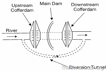
4. COFFER DAM
5. DEBRIS DAM

1. STORAGE DAM OR IMPOUNDING DAM

It is constructed to create a reservoir to store water during periods when there is huge flow in the river (in excess of demand) for utilisation later during periods of low flow (demand exceeds flow in the river). Water stored in the reservoir is used for irrigation, power generation, water supply etc. By suitable operation, it can also serve as a detention dam.

2. DETENTION DAM

It is primarily constructed to temporarily detain all or part of the flood water in a river and to gradually release the stored water later at controlled rates so that the entire region on the downstream side of the dam is protected from possible damage due to floods. It may also be used as a storage dam.

3. DIVERSION DAM

It is constructed to divert part of or all the water from a river into a conduit or a channel. For diverting water from a river into an irrigation canal, mostly a diversion weir is constructed across the river.

4. COFFER DAM

It is a temporary dam constructed to exclude water from a specific area. It is constructed on the u/s side of the site where a dam is to be constructed so that the site is dry. In this case, it behaves like a diversion dam.

5. DEBRIS DAM

It is constructed to catch and retain debris flowing in a river.
Dam Construction
Figure: Dam Construction

BASED ON HYDRAULIC DESIGN

1. OVERFLOW DAM OR OVERFALL DAM

It is constructed with a crest to permit overflow of surplus water that cannot be retained in the reservoir. Generally dams are not designed as overflow dams for its entire length. Diversion weirs of small height may be designed to permit overflow over its entire length.

2. NON-OVERFLOW DAM

It is constructed such that water is not allowed to overflow over its crest.
In most cases, dams are so designed that part of its length is designed as an overflow dam (this part is called the spillway) while the rest of its length is designed as a non-overflow dam. In some cases, these two sections are not combined.

BASED ON MATERIAL OF CONSTRUCTION

1. RIGID DAM

It is constructed with rigid material such as stone, masonry, concrete, steel, or timber. Steel dams (steel plates supported on inclined struts) and timber dams (wooden planks supported on a wooden framework) are constructed only for small heights (rarely).

2. NON-RIGID DAM (EMBANKMENT DAMS)

It is constructed with non-rigid material such as earth, tailings, rockfill etc.
  • Earthen dam – gravel, sand, silt, clay etc
  • Tailings dam – waste or refuse obtained from mines
  • Rockfill dam – rock material supporting a water tight material on the u/s face
  • Rockfill composite dam – Rockfill on the d/s side and earth fill on the u/s side
  • Earthen dams are provided with a stone masonry or concrete overflow (spillway) section. Such dams are called composite dams.
  • In some cases, part of the length of the dam is constructed as earth dam and the rest (excluding the spillway) as a masonry dam. Such dams are called masonry cum earthen dams.

BASED ON STRUCTURAL BEHAVIOUR

  • GRAVITY DAM
  • ARCH DAM
  • BUTTRESS DAM
  • EMBANKMENT DAM

GRAVITY DAM

It is a masonry or concrete dam which resists the forces acting on it by its own weight. Its c/s is approximately triangular in shape.
Straight gravity dam – A gravity dam that is straight in plan.
Curved gravity plan – A gravity dam that is curved in plan.
Curved gravity dam (Arch gravity dam) – It resists the forces acting on it by combined gravity action (its own weight) and arch action.
Solid gravity dam – Its body consists of a solid mass of masonry or concrete
Hollow gravity dam – It has hollow spaces within its body.
Most gravity dams are straight solid gravity dams.
Concrete Gravity Dams
  • Weight holds dam in place
  • Lots of concrete (expensive)
concrete gravity dam
These dams are heavy and massive wall-like structures of concrete in which the whole weight acts vertically downwards
Gravity Dam
As the entire load is transmitted on the small area of foundation, such dams are constructed where rocks are competent and stable.
  • Bhakra Dam is the highest Concrete Gravity dam in Asia and the second highest in the world.
  • Bhakra Dam is across river Sutlej in Himachal Pradesh
  • The construction of this project was started in the year 1948 and was completed in 1963 .
  • It is 740 ft. high above the deepest foundation as straight concrete dam being more than three times the height of Qutab Minar.
  • Length at top 518.16m (1700 feet); width at base 190.5m (625 feet), and at the top is 9.14m (30 feet)
  • Bhakra Dam is the highest Concrete Gravity dam in Asia and Second Highest in the world.
Bhakra Dam
Bhakra Dam
Bhakra Dam

2. ARCH DAM

It is a curved masonry or concrete dam, convex upstream, which resists the forces acting on it by arch action.
The only arch dam in India – Idukki dam (double curvature in plan) – concrete arch dam
Arch Dams
  • Arch shape gives strength
  • Less material (cheaper)
  • Narrow sites
  • Need strong abutments
Arch Dam
  • These type of dams are concrete or masonry dams which are curved or convex upstream in plan
  • This shape helps to transmit the major part of the water load to the abutments
  • Arch dams are built across narrow, deep river gorges, but now in recent years they have been considered even for little wider valleys.
Arch Dam
Arch Dam
  • Good for narrow, rocky locations.
  • They are curved and the natural shape of the arch holds back the water in the reservoir.
  • Arch dams, like the El Atazar Dam in Spain, are thin and require less material than any other type of dam.
Idukki Arch Dam
Arch Dam
Arch Dam

3. BUTTRESS DAM

It consists of water retaining sloping membrane or deck on the u/s which is supported by a series of buttresses. These buttresses are in the form of equally spaced triangular masonry or reinforced concrete walls or counterforts. The sloping membrane is usually a reinforced concrete slab. In some cases, the u/s slab is replaced by multiple arches supported on buttresses (multiple arch buttress dam) or by flaring the u/s edge of the buttresses to span the distance between the buttresses (bulkhead buttress dam or massive head buttress dam). In general, the structural behaviour of a buttress dam is similar to that of a gravity dam.
Buttress Dams
  • Face is held up by a series of supports
  • Flat or curved face
Buttress Dams
  • Buttress Dam – Is a gravity dam reinforced by structural supports
  • Buttress – a support that transmits a force from a roof or wall to another supporting structure
  • This type of structure can be considered even if the foundation rocks are little weaker.
Buttress Dams
Buttress Dams

4. EMBANKMENT DAM

It is a non-rigid dam which resists the forces acting on it by its shear strength and to some extent also by its own weight (gravity). Its structural behaviour is in many ways different from that of a gravity dam.
  • Earth or rock
  • Weight resists flow of water
EMBANKMENT DAM
Earth Dams
  • They are trapezoidal in shape.
  • Earth dams are constructed where the foundation or the underlying material or rocks are weak to support the masonry dam or where the suitable competent rocks are at greater depth.
  • Earthen dams are relatively smaller in height and broad at the base.
  • They are mainly built with clay, sand and gravel, hence they are also known as Earth fill dam or Rock fill dam.
Earth Dams
EMBANKMENT DAM - Earth Dam
Embankment dams are also armed with a dense, waterproof core that prevents water from seeping through the structure.

BASED ON SIZE (HYDRAULIC HEAD AND GROSS STORAGE IN THE RESERVOIR BEHIND THE DAM)


Sl. No.

Classification

Gross Storage

(MCM)

Hydraulic Head (m)

1

Small

0.50 – 10.00

7.5 – 12.0

2

Intermediate

10.00 – 60.00

12.0 – 30.0

3

Large

> 60.00

> 30


FORCES ACTING ON A DAM STRUCTURE


www,searchtapari.in           
In the design of a dam, the first step is the determination of various forces which acts on the structure and study their nature. Depending upon the situation, the dam is subjected to the following forces:
1. Water pressure
3. Silt pressure
4. Wave pressure
5. Ice pressure
6. Self weight of the dam.
The forces are considered to act per unit length of the dam.
For perfect and most accurate design, the effect of all the forces should be investigated. Out of these forces, most common and important forces are water pressure and self weight of the dam.

1. Water Pressure

Water pressure may be subdivided into the following two categories:
I) External water pressure:
It is the pressure of water on the upstream face of the dam. In this, there are two cases:
(i) Upstream face of the dam is vertical and there is no water on the downstream side of the dam (figure 1).
External water pressure on dam
Figure 1
The total pressure is in horizontal direction and acts on the upstream face at a height  from the bottom. The pressure diagram is triangular and the total pressure is given by
Where w is the specific weight of water. Usually it is taken as unity.
H is the height upto which water is stored in m.
(ii) Upstream face with batter and there is no water on the downstream side (figure 2).
FORCES ACTING ON A DAM STRUCTURE
Figure 2
Here in addition to the horizontal water pressure  as in the previous case, there is vertical pressure of the water. It is due to the water column resting on the upstream sloping side.
The vertical pressure  acts on the length ‘b’ portion of the base. This vertical pressure is given by
Pressure  acts through the centre of gravity of the water column resting on the sloping upstream face.
If there is water standing on the downstream side of the dam, pressure may be calculated similarly. The water pressure on the downstream face actually stabilizes the dam. Hence as an additional factor of safety, it may be neglected.
II) Water pressure below the base of the dam or Uplift pressure
When the water is stored on the upstream side of a dam there exists a head of water equal to the height upto which the water is stored. This water enters the pores and fissures of the foundation material under pressure. It also enters the joint between the dam and the foundation at the base and the pores of the dam itself. This water then seeps through and tries to emerge out on the downstream end. The seeping water creates hydraulic gradient between the upstream and downstream side of the dam. This hydraulic gradient causes vertical upward pressure. The upward pressure is known as uplift. Uplift reduces the effective weight of the structure and consequently the restoring force is reduced. It is essential to study the nature of uplift and also some methods will have to be devised to reduce the uplift pressure value.
Water pressure below the base of the dam or Uplift pressure
Figure 3
With reference to figure 3, uplift pressure is given by
Where clip_image020 is the uplift pressure, B is the base width of the dam and H is the height upto which water is stored.
This total uplift acts at  from the heel or upstream end of the dam.
Uplift is generally reduced by providing drainage pipes or holes in the dam section.
Self weight of the dam is the only largest force which stabilizes the structure. The total weight of the dam is supposed to act through the centre of gravity of the dam section in vertically downward direction. Naturally when specific weight of the material of construction is high, restoring force will be more. Construction material is so chosen that the density of the material is about 2.045 gram per cubic meter.

2. Earthquake Forces

The effect of earthquake is equivalent to an acceleration to the foundation of the dam in the direction in which the wave is travelling at the moment. Earthquake wave may move in any direction and for design purposes, it is resolved into the vertical and horizontal directions. On an average, a value of 0.1 to 0.15g (where g = acceleration due to gravity) is generally sufficient for high dams in seismic zones. In extremely seismic regions and in conservative designs, even a value of 0.3g may sometimes by adopted.
Vertical acceleration reduces the unit weight of the dam material and that of water is to clip_image024 times the original unit weight, where clip_image026 is the value of g accounted against earthquake forces, i.e. 0.1 when 0.1g is accounted for earthquake forces. The horizontal acceleration acting towards the reservoir causes a momentary increase in water pressure and the foundation and dam accelerate towards the reservoir and the water resists the movement owing to its inertia. The extra pressure exerted by this process is known as hydrodynamic pressure.

3. Silt Pressure

If h is the height of silt deposited, then the forces exerted by this silt in addition to the external water pressure, can be represented by Rankine formula
 acting at clip_image030 from the base.
Where,
clip_image032= coefficient of active earth pressure of silt = 
clip_image036 = angle of internal friction of soil, cohesion neglected.
clip_image038= submerged unit weight of silt material.
h = height of silt deposited.

4. Wave Pressure

Waves are generated on the surface of the reservoir by the blowing winds, which exert a pressure on the downstream side. Wave pressure depends upon wave height which is given by the equation
 for F < 32 km, and
 for F > 32 km
Where clip_image044is the height of water from the top of crest to bottom of trough in meters.
V – wind velocity in km/hour
F – fetch or straight length of water expanse in km.
The maximum pressure intensity due to wave action may be given by
 and acts at  meters above the still water surface.
Wave pressure on Dam
Figure 4
The pressure distribution may be assumed to be triangular of height  as shown in figure 4.
Hence total force due to wave action 
 acting at  above the reservoir surface.

5. Ice Pressure

The ice which may be formed on the water surface of the reservoir in cold countries may sometimes melt and expand. The dam face is subjected to the thrust and exerted by the expanding ice. This force acts linearly along the length of the dam and at the reservoir level. The magnitude of this force varies from 250 to 1500 kN/sq.m depending upon the temperature variations. On an average, a value of 500 kN/sq.m may be taken under ordinary circumstances.

6. Weight of dam

The weight of dam and its foundation is a major resisting force. In two dimensional analysis of dam, unit length is considered.

Tuesday 9 December 2014

Burj Khalifa-Dubai

 Burj Khalifa.jpg www.searchtapari.in


Burj Dubai
Record height
Tallest in the world since 2010[I]
Preceded by Taipei 101
General information
Type Mixed-use
Location Dubai, United Arab Emirates
Coordinates 25°11′49.7″N 55°16′26.8″ECoordinates: 25°11′49.7″N 55°16′26.8″E
Construction started 6 January 2004
Completed 2010
Opening 4 January 2010[1]
Cost USD $ 1.5 billion[2]
Height
Architectural 828 m (2,717 ft)[3]
Tip 829.8 m (2,722 ft)[3]
Roof 828 m (2,717 ft)[3]
Top floor 584.5 m (1,918 ft)[3]
Observatory 452.1 m (1,483 ft)[3]
Technical details
Floor count 163 floors[3][4]
plus 46 maintenance levels in the spire[5] and 2 parking levels in the basement
Floor area 309,473 m2 (3,331,100 sq ft)[3]
Design and construction
Architect Adrian Smith at SOM
Developer Emaar Properties[3]
Structural engineer Bill Baker at SOM[6]
Main contractor Samsung Engineering and Construction Company, Besix and Arabtec
Supervision Consultant Engineer & Architect of Record Hyder Consulting
Construction Project Manager Turner Construction
Grocon[7]
Planning Bauer AG and Middle East Foundations[7]
Lift contractor Otis[7]
VT consultant Lerch Bates[7]